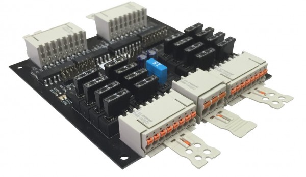
Fuse and amplifier circuit
The fuse and amplifier circuit can be used for various purposes:
- amplify the power of a coupling circuit / key contacts for e.g. controlling double stop magnets and secure them simultaneously.
- To secure an organ with electric keys and stop action and the associated historical console,
and so on.
A circuit has 16 inputs and outputs.
The circuit is controlled via a 12VDC - 28VDC input voltage. Key contacts for example, can be connected here. Hereafter, they only have to switch a few milliamperes.
+ and - are connected via another circuit (load circuit). This circuit is used to switch the applied voltage through the outputs when the associated input is switched.
Each output is fused with a 1A ATM fuse.
Each circuit is fused with a 15A ATM fuse.
A rail carrier on the aluminum housing allows the space-saving installation of the components.
Spring clamp push-in technology on the detachable plugs allows the insertion of rigid conductors as well as conductors with wire end ferrule without any additional tools. To insert flexible conductors or disconnect the conductors, press the release button.
With a cable tie, the cable can be attached to the handle plates mounted on the connector for easy strain relief.
It is possible to have plus and minus supply terminals up to a maximum of 2.5mm² cable.
Input and output terminals possible up to a minimum of 0.14mm².
Solderless connections
Control via 14-28VDC
Plug included.
To unlock the connector, slide the orange slider on the underside of the handle plate toward the connector body.
Circuit board dimensions: 100x100x20mm (+ 20mm plug handle plate, each side = 140x100x15mm) Case dimensions: 105x105x65mm (+ 20mm male handle, each side = 145x105x65mm)
Input voltage and operating voltage may differ. For example, it is possible to use 24V operating voltage and 14V input voltage (or vice versa).
No external voltage higher than the operating voltage or when the circuit is switched off may be applied to the outputs. This leads to damage of the circuit board.
Attention: Differing from the photo, the housings are anodized blue.


